

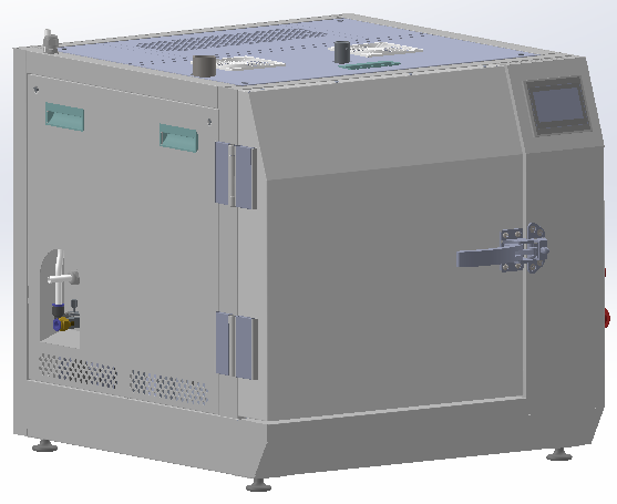
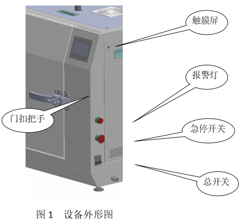
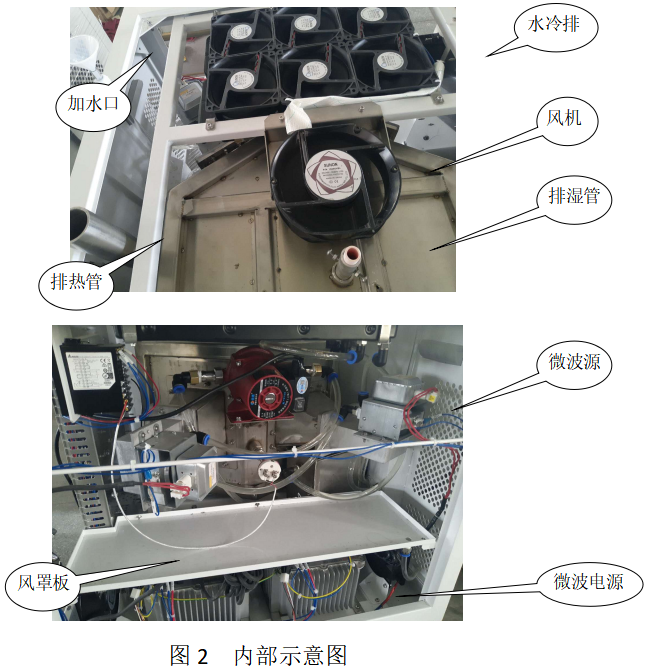
The box-type furnace is mainly composed of furnace body, cabinet, heat preservation system, control system, microwave source, thermocouple, etc. (see Figure 1, overall structure diagram and Figure 2 outline diagram). The oven door is embedded in the cabinet and is flush with the cabinet. The top of the furnace is provided with an exhaust window; the rear of the furnace is provided with a microwave source and a microwave power supply; the right part is provided with an electronic control installation board, an electronic control system and a thermometer, and the interior of the furnace contains a thermal insulation molding module.
The furnace body is all made of SUS304 stainless steel. They are respectively composed of furnace chamber, furnace door switch automatic circuit breaker, dehumidification window, temperature measurement interface and microwave feed inlet.
There is a furnace door safety interlock device (furnace door switch automatic circuit breaker) on the right side. The left side is equipped with a heat exhaust device, the bottom is equipped with an air cooler that is turned on when the temperature is lowered, the top is equipped with a moisture exhaust pipe, and the rear is equipped with staggered microwave sources and thermocouples.
The inner surface of the furnace door is equipped with thermal insulation cotton blocks and microwave shielding strips, and is equipped with heat insulation clips to prevent the furnace door from being hot when the temperature is high.
Only by fitting the furnace door with the flange surface of the furnace chamber and locking the furnace door, the microwave source can work normally. When opening the furnace door, pull the handle of the door buckle. Once the furnace door does not fit the flange surface of the furnace cavity, the interlocking device will cut off the microwave power immediately, and the microwave source will stop working instantly.
The cabinet is a frame structure, with detachable sealing plates on the left, right, top and back. Each sealing plate is provided with ventilation mesh holes and handles for easy maintenance.
The thermal insulation system consists of thermal insulation molding modules of ceramic fibers, auxiliary heating plates, etc. There is a vent hole at the top.
The microwave conduction system is equipped with 2 sets of 1.5kW microwave heads and microwave high-voltage power supplies. The microwave feeding flange is facing the cavity, and the outlet is made of PTFE plate as a blind plate to prevent exhaust gas and dust from entering the microwave head. Affect the service life of the microwave source.
Cooling water system
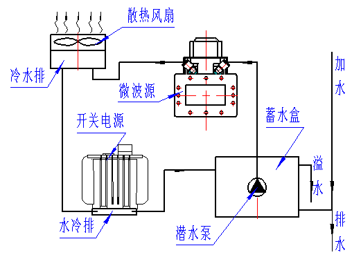
The magnetron of the microwave source provides cooling water, which effectively prolongs the service life of the magnetron. The cooling water system is composed of a water storage box, a submersible pump, a cold water drain, a water cooling drain, an axial flow fan, a connecting pipe, a quick-connect joint, etc. Control the water jacket, then enter the cold water row to dissipate heat through the axial flow fan, then flow through the water cooling row at the bottom of the switching power supply, and finally return to the water storage box. The water filling port on the left adds water to the water storage box. When it is added to the height of the overflow port of the water storage box, the excess water flows from the overflow pipe to the outside of the equipment. When the equipment is not used for a long time, the locking sleeve can be released to add water Rotate down to drain and also need to pull out the connecting pipe between the booster pump and the microwave source from the push-in connector for draining.
The control system consists of a power supply control circuit, an alarm circuit, a temperature measurement circuit and a display device. Display, control, adjustment and switch are all controlled by the touch screen mounted on the front panel.
The electrical operating components visible outside the equipment include touch screen, sound and light alarm indicator, system emergency stop button and equipment power switch. The touch screen is located on the operation panel in the upper right corner of the equipment, and the right side of the equipment near the furnace is light and sound from top to bottom. Alarm indicator light, system emergency stop button and equipment power switch.
The touch screen is used to set and display various parameters, check alarm information and issue operating instructions.
Alarm indicator light: When the indicator light flashes and rings, it means that the equipment has detected a fault alarm; when the indicator light is off (without clicking the "Audio Alarm Release" soft key on the touch screen), it means that the system has no abnormality , works normally.
Emergency stop (red grinding head) button: When the equipment works abnormally, press this button, the equipment will stop running immediately (including microwave source, forced cooling fan). After the emergency stop button is manually reset, the equipment will still be in the state of stopping heating; if you want to restart the system, please restart the operation.
Note: While the emergency stop button is being pressed, tapping the system start button on the touch screen will not start heating.
Equipment power switch: It is used to connect and disconnect the internal power supply of the equipment. The switch handle is turned up to turn on, and turned down to turn off. During normal operation, both switches are required to be in the on position.
 Add:
Add:  Tel: 183-8269-6252
 Online consultation:
  E-mail: Lynn@winsplas.com